Breaking the Flash Encryption Feature of Espressif’s Parts
Posted on Mon 08 January 2024 in Projects
Introduction
I recently read the Unlimited Results: Breaking Firmware Encryption of ESP32-V3 (Abdellatif et al., 2023) paper.
This paper is about breaking the firmware encryption feature of the ESP32 SoC using a Side-Channel attack.
This was an interesting read, and soon, I wanted to try to reproduce these results with the following constraints:
- To understand everything about this attack, I wanted to start from scratch, even if it meant sometimes reinventing the wheel.
- I wanted to keep things low-cost. This means no five-figure digital oscilloscope could be used, as it’s sometimes the case for such attacks.
A few weeks later, not only have I been able to reproduce the paper’s results regarding the ESP32, but I have also:
- Mounted a similar attack against the
ESP32-C3andESP32-C6. - Mounted a secure boot bypass attack based on voltage glitches for both the
ESP32-C3andESP32-C6.
The first article will detail the side-channel attacks, starting from the basics. A second one will focus on Secure Boot bypass techniques.
Side-Channel Attack Basics
This section will hopefully provide enough theoretical knowledge about side-channel attacks for the rest of the article to make sense. Of course, this topic is extremely broad, so I’ll only scratch the surface of many concepts. Anyone already familiar with the topic should feel free to skip this introduction.
General Idea
A side-channel attack exploits unintentional information leakage from a system to uncover secret values, typically encryption keys. The side channel can take various forms, including timing variations or the power consumption of a device. All the attacks presented in this article will focus on power consumption.
The general idea is to allow the target device to perform an operation involving the secret data we want to recover, along with attacker-supplied data. During this operation, the current consumed by the device is measured. A simple shunt resistor can be used to perform the measurement.
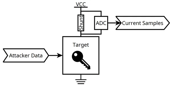
If the target device happens to be “leaky”, the measured current is influenced by the value of the manipulated secret to some extent.
To take advantage of this leakage, the following steps are necessary:
- Assume a power consumption model: a mathematical representation connecting a specific secret value to a variation in power consumption.
- Utilize some kind of mathematical tool to assess how closely a particular secret value aligns with the selected power consumption model.
The next sections of this article will introduce commonly used power consumption models as well as a mathematical tool, the Correlation Power Analysis method.
Power Consumption Models
Hamming Weight Model
Internally, our targets mostly operate on synchronous logic. This means that for each system clock cycle, internal registers are updated.
For each register, it is assumed that differences between the original and new values of each individual bit contribute to the total power consumption.
A common assumption is that it consumes more to change a value. Hence:
- increases the power consumption.
- increases the power consumption as well.
- However, and don’t.
Using a more formal approach, it’s possible to express that the power consumption of a given register updating from a value to a value is:
Where is the Hamming Weight function, which simply counts the number of ones in the binary representation of a number.
Example: AES First Round Encryption
Now, how could this be applied to, for instance, a leaky hardware cryptographic encryption core?
Let’s consider the following situation:
- An attacker can input arbitrary values into the encryption core.
- The encryption core encrypts these values with a secret key. The algorithm used is assumed to be AES-128.
The following diagram summarizes the AES-128 algorithm.
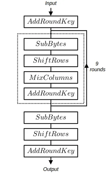
The details of each operation can be found on the dedicated Wikipedia AES page. For this section, at least the operations and need to be understood.
If we assume a register to be connected just after the SubBytes operation, the value of this register can be defined as:
Where:
- is the attacker-controlled plaintext.
- is the first round encryption key, corresponding to the AES-128 secret encryption key.
- : the standard Rijndael S-box lookup table.
Note that while is 128-bit long, it’s also possible to consider 8-bit slices and define:
During this register update, the power consumption can be modeled as:
Assuming the initial values to be zeros, we simply obtain:
Having divided the state register into slices can be used as a divide and conquer method.
For the attacker, the goal will be, for each byte of the secret key , to find the best matching defined as:
With .
Note
Choosing to attack the output of the Rijndael S-box lookup table is done on purpose. The input and output of these tables are not linearly related, making the difference between valid and “almost valid” guesses very noticeable.
What’s now missing is a mathematical tool that can be used to quantify how well a given guess is matching with the sampled power traces.
Correlation Power Analysis
Let’s consider that power consumption traces have been sampled while processing the corresponding plaintext values. Moreover, a power consumption model has been chosen.
We unfortunately don’t precisely know when (i.e., for which value) the leakage occurs. Hence, for all possible and values, we need to quantify the correlations between the arrays and defined as:
The commonly used mathematical tool for the task is the Pearson correlation coefficient. Coefficients are computed for all and values.
The largest of these coefficients will give:
- The value at which the leakage occurs.
- The valid guess.
The following animation summarizes the Correlation Power Analysis method.
Espressif’s Flash Encryption Feature
Overview
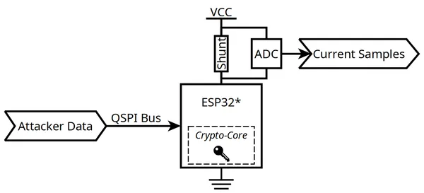
At the highest level, the external flash encryption feature implemented for the ESP32, ESP32-C3 and ESP32-C6 is essentially the same.
The external flash contains the entire firmware executed by the chip. It’s accessed via a QSPI bus.
Note
The components I targeted are all using external QSPI flash components. This means it’s reasonably easy for an attacker to directly tamper with the QSPI bus.
Espressif’s portfolio also contains SoC with internal flash components. This could make the methods presented here impractical. However, it is to be noted that some of these components still expose the internal flash’s pinout to the outside. It means there may still be a way to make things work. Nevertheless, that’s outside the scope of this article.
This feature can be enabled by configuring some of the device’s eFuses. A secret encryption key is burned into them.
Once activated, the content of the external flash content is transparently and automatically decrypted as soon as it is accessed. The decryption is performed by a dedicated hardware block.
For all devices, the AES cipher is used. However, the cipher mode of operation differs and will be detailed for each chip later in this article.
High-Level Attack Plan
Attacking the ESP32, ESP32-C3 and ESP32-C6 is a textbook side-channel attack where:
- The secret to be recovered is obviously related to the AES key burned into the fuses.
- The attacker can provide arbitrary inputs by tampering with the data read by the target chip over its QSPI bus.
It is to be noted that a physical flash component cannot be utilized. Such a memory indeed has:
- A slow erase and write speed that would slow down the attack.
- A limited number of erase cycles that would make the attack impracticable.
Instead, some kind of hardware should be used to emulate a flash component over the QSPI bus.
Hardware Platform
Schematics and other hardware-related documents are available on the dedicated hardware files page.
Goals
To perform a side-channel attack against the ESP32 family of devices, the following is needed:
- The target needs to be supplied with arbitrary flash content through its QSPI bus.
- The power consumption of the target needs to be monitored.
- Timing and synchronization are critical. Full control over the target’s clock is needed.
Furthermore, as mentioned earlier, cost should be kept low.
Overview
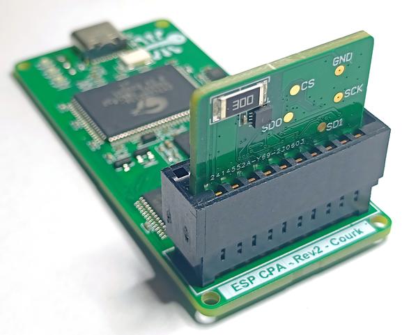
Based on the previous goals and constraints, the following hardware platform, called the ESP CPA Board, has been designed.
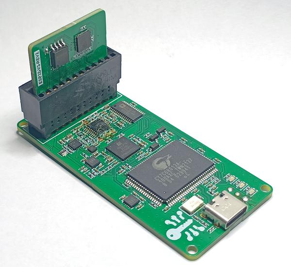
This is a simple 4-layer board that can be assembled manually. Additionally, even for small order quantities, the total BOM cost barely exceeds $100.
Note
In the picture above, you may notice that this revision of the board has been reworked due to a minor layout mistake. However, the hardware files I’m sharing already have this problem fixed.
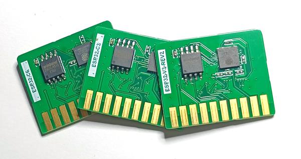
Small daughter-boards, called “cartridges” can be plugged to the ESP CPA Board.
As you may have guessed already, I’ve designed a “cartridge” for each of our targets, namely the ESP32, ESP32-C3 and ESP32-C6.
Block Diagram
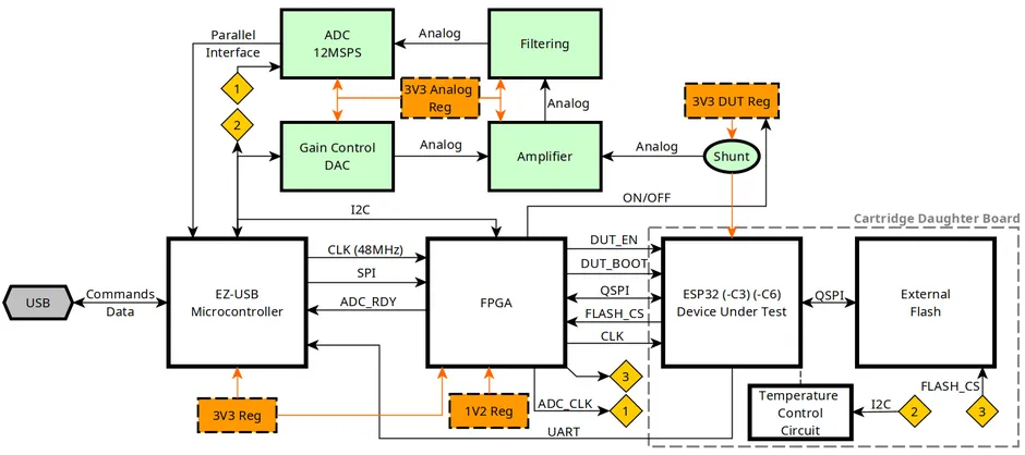
The main functional blocks of the ESP CPA Board are detailed below.
Key Features
Fake External Flash
The flash content provided to the DUT can either be fed from a physical flash component, placed on the cartridge or faked from the FPGA. This is achieved by letting the FPGA control the Chip Select line of the “real” flash.
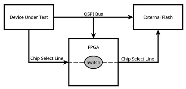
Such a feature is needed to easily and quickly supply arbitrary data to be decrypted by the DUT hardware crypto-core.
Current Measurement
The current consumed by the DUT can be sampled thanks to an ADC. A simple current shunt along with a variable gain amplifier and some antialiasing filtering is used.
To keep costs reasonable, the sampling rate of this acquisition chain is only . This may sound too low, but that’s actually fine, considering it’s possible to under-clock Espressif’s parts.
Clock Control
The clock of the DUT is provided by the FPGA.
While Espressif’s components typically expect a crystal oscillator, I’ve found feeding a digital clock works as well.
Note
It seems the clock can be fed directly at LVCMOS levels for both the ESP32 and ESP32-C3. However, for the ESP32-C6, capacitively coupling this clock signal seems to be needed for everything to work as expected.
This allows for total control over this clock, and down-clocking the DUT becomes possible. As stated above, this is very useful given the low sampling rate of the current measurement acquisition chain. However, reducing the clock speed introduces the trade-off of extending the duration of our attacks. As I’ll explain later, certain targets required up to five days to be compromised.
Temperature Control
During my tests, I’ve found some targets, especially the ESP32, to be rather sensitive to temperature variation.
The above diagram, captured from a ESP32, demonstrates the phenomena. The temperature is displayed, alongside samples from various measurements, captured at the same time offset.
This variability could degrade the performance of the side-channel attack. That’s the reason, on the back of each cartridge, it’s possible to find:
- A low-value resistor that acts as a heating element.
- A temperature sensor placed just below the DUT.
These two components are used to precisely control the temperature of the DUT, keeping it stable, slightly above ambient. Thanks to a simple PID controller, a value of was maintained for all the results presented here.
This technique is inspired from crystal ovens.
Software Support
All the software components of this project are available from this repository.
Firmware & Gateware
Two programmable components are mounted on the ESP CPA Board.
The first one, a microcontroller, the Cypress EZ-USB FX2 (CY7C68013A-100AXC) is used to:
- Sample and stream the data from the ADC.
- Configure and communicate with the FPGA.
The firmware of this component is written in C and based on libfx2.
The second one is an FPGA, a small ICE5LP1K. This component is well-supported by an open-source toolchain, making it enjoyable to use.
Its gateware is entirely described in Python with Amaranth HDL.
Host Software
The host software is composed of several tools that can be used to:
- Configure and control the ESP CPA Board.
- Store the data sampled by the ESP CPA Board.
- Analyze the sampled data with Correlation Power Analysis techniques.
- Display the results of the analysis on a graph.
Most of these tools are written in Python, but some computationally intensive analysis sections are offloaded to a piece of Rust code.
Furthermore, the hardware can be configured to be compatible with Espressif’s development tools. It makes flashing a firmware on the DUT, or burning its security-related fuses, convenient.
Attacking the ESP32
Here, the results of Unlimited Results: Breaking Firmware Encryption of ESP32-V3 (Abdellatif et al., 2023) are successfully replicated thanks to the ESP CPA Board. As this is not something new, certain details may be glossed over, and I encourage you to read the paper for additional insights.
Encryption Method Overview
The encryption method used by the ESP32 is thoroughly explained in the official documentation.
What’s important to grasp is that:
- The
ESP32flash encryption feature is built upon the AES-256 cipher. - While the flash content is semantically decrypted, the hardware itself performs AES encryption. According to Espressif, this is done for performance reasons.
- The main encryption key is stored in the fuses.
- Each 32-byte block of flash data is encrypted with a distinct key, derived from these fuses. This key is said to be tweaked with the flash address.
In the context of our side-channel attack, this tweak mechanism doesn’t add much value. For instance, recovering the tweaked key of the first 32-byte block is sufficient to compute the main key.
On the other hand, the AES-256 cipher requires attacking two AES rounds to recover the entire key. 128 bits per round can be recovered.
Experimental Results
Traces Capture
I started by burning the fuses of my target ESP32, mounted on a cartridge board, to enable the flash encryption feature with a known key. This can be done by following the official documentation.
Next, I performed the actual measurement campaign.
It means the DUT has been fed arbitrary data thanks to the Fake Flash feature of the ESP CPA Board, while its power consumption has been sampled.
Each measurement cycle is performed as follows:
- The FPGA Fake Flash is configured with a given 128-bit long random ciphertext. These bits will be read by the DUT at boot. More precisely, the Boot ROM firmware of the DUT will pull this data from the flash.
- The DUT reset line is released.
- As soon as the FPGA can detect the arbitrary 128 bits have been read, the current measurement ADC is sampled for a couple of DUT clock cycles.
Hence, the current traces are captured at around the time the hardware crypto-core of the DUT is processing the provided data.
For better vertical resolution, the procedure is repeated 8 times for a given ciphertext. Samples are next averaged.
Traces corresponding to 600k unique ciphertexts have been recorded.
Traces Analysis
Some basic pre-processing methods are first applied to the measured traces. For instance, a Butterworth digital band-pass filter is used to denoise the signal.
Next, I used the same CPA attack described in the Unlimited Results: Breaking Firmware Encryption of ESP32-V3 (Abdellatif et al., 2023) paper.
I won’t go into many details as this is not something new, just note that the leakage model used for the first round is:
This is similar to the model I introduced in the first section of this article. Moving forward, for the second round, the leakage is defined as follows:
With:
- : the Hamming Weight function.
- : the standard Rijndael S-box lookup table.
- : the index of the index of key byte being attacked.
- : the arbitrary ciphertext provided by the Fake Flash component of the ESP CPA Board.
- : the output of the first AES decryption round. This can be computed given the key recovered by attacking the first round.
- : the guessed first round key.
Performing the attack results in both the first and second round keys being successfully recovered.
The following graphs, that will be widely used in the remaining sections of this article, display the ranking evolution for each guess.
Arranging the correlation values in descending order for each key byte enables the ranking of all guesses. A rank of zero for a known-good guess (i.e., the correct guess has the highest correlation value) means the attack converged toward a correct result.
Of course, such a graph can only be obtained when the key is known beforehand. It’s a tool that can only be used for evaluating a side-channel attack.
Alternatively, it’s also possible to take a look at the values of the correlation coefficients. The coefficients of the correct key bytes are rapidly increasing, demonstrating that the attack is a success.
Detailed results for this attack, as well as supplementary information, are available on the ESP32 Detailed Results page.
Conclusion
Thanks to the ESP CPA Board, I was able to reproduce results from the Unlimited Results: Breaking Firmware Encryption of ESP32-V3 (Abdellatif et al., 2023) paper at a significantly lower cost.
These initial experiments did not yield any new discoveries, but they did validate both the ESP CPA Board hardware and the related analysis software.
Attacking the ESP32-C3
Next target, the ESP32-C3.
After the publication of the Unlimited Results: Breaking Firmware Encryption of ESP32-V3 (Abdellatif et al., 2023) paper that inspired my research, Espressif published a security advisory: Security Advisory Concerning Breaking the Hardware AES Core and Firmware Encryption of ESP32 Chip Revision v3.0.
The document states:
For hardware Flash encryption of ESP32-S2, ESP32-S3, ESP32-C3, ESP32-C2, the encryption algorithm has been upgraded to a more complex XTS-AES scheme; it increases the difficulty and cost of mounting an SCA, and hence, reduces security risks.
Hence, I knew what to expect. Attacking the device was likely possible, but could be more complicated because of the use of the XTS mode.
Encryption Method Overview
Find below a block diagram for the decryption path of the XTS mode, as used by the ESP32-C3.
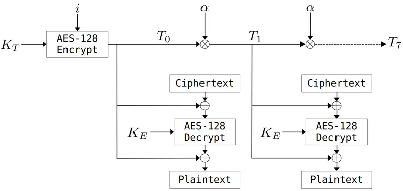
Two AES encryption blocks are employed, each with a distinct key:
- The first key, , will also be called the tweak key.
- The second one, .
On the ESP32-C3, both and are 128-bit long and read from the fuses.
The value does depend on the flash address the data is pulled from. It is incremented every 0x80 bytes. is encrypted with to obtain a value, , that we’ll call the initial tweak value.
For each of the eight 128-bit blocks composing the 128 bytes where is constant, can be computed from based on the following relationship.
Here, the operator corresponds to a Galois field multiplication and to the number in such a field. I’m not a cryptographer and won’t attempt to explain why this is useful and the theoretical details behind it. For our purpose, what’s important to understand is that this operation can be reversed.
The tweak values are xor’ed at the input and output of the encryption block that uses the key.
Attack Plan
As expected, attacking such a cipher mode poses challenges. The most obvious one is that we don’t have a single key to guess, but two independent keys.
Recovering seems particularly challenging, given the limited control we have over the value of .
However, the approach I am about to present draws inspiration (albeit loosely, as I won’t be following the exact same procedure) from the paper Side-channel power analysis of XTS-AES (Luo et al., 2017) and can help us extract enough information to recover:
- The value of .
- The values of all corresponding to a given .
This is sufficient to decrypt the 128-byte block associated with a specific .
Of course, this also implies that decrypting the entire flash content might require a successful CPA attack for every 128-byte blocks. My next article details how to overcome this limitation.
“Tweaked” Key Recovery
First, let’s define as the tweaked key of the first decryption round of the block.
Where:
- corresponds to the decryption key of the first AES decryption round. Hence, it’s the last key of the AES key schedule that starts with .
- corresponds to the tweak value at the flash offset the CPA attack will be performed at.
Assuming a successful CPA attack, we can assume that recovering the value of is possible.
However, this value alone isn’t enough to decrypt the flash content. Going further is needed.
Second round Key Recovery
With known, it’s possible to attack, once more with CPA methods, the second round of the decryption block.
Obtaining the key of this next round directly isn’t possible. However, what’s possible is to recover defined as:
Where:
- is the decryption key for the second decryption round.
- is the standard AES column mixing operation.
See this article to understand why such a transformation is useful.
Recovery
Given , can be obtained by applying the operation.
Next, reversing the AES key schedule provides access to all round keys. As an AES-128 block is used, the first key of the schedule, , is equal to .
Recovery
Given:
- The relation .
- The known value .
- The known value (all the round keys have been recovered just above).
Using the following formula provides access to .
Now, how to obtain all tweak values, given ? Well, remembering the following relationship:
And the fact can be reversed, computing all values becomes possible.
Leakage Model
First Decryption Round
Now that we understand the type of key-related information to retrieve, mounting a CPA attacks could look a lot like what has been done against the ESP32.
However, there’s an important difference to consider: the leakage model. The ESP32-C3 is actually using decryption, contrary to the ESP32 where, even though the flash was semantically decrypted, encryption blocks were used.
At first, ones could speculate that employing a model such as:
instead of:
could work. It actually doesn’t.
This is probably due to the fact that the hardware implementation of the ESP32-C3 is reasonably optimized, and the output of the inverted table doesn’t directly appear in a register.
Instead, I hypothesize the hardware implementation is based on T-Tables, an optimized AES computation method. See this great article for more details.
After some trial and error and based on this assumption, I came up with the following first decryption round power leakage model.
Where:
- is the supplied ciphertext.
- is the index of the byte being guessed ( ).
- are guesses at byte index for the previous defined .
- is the number 9 in .
- is the number 11 in .
- is the number 13 in .
- is the number 14 in .
This may sound complex, but this simply translates the utilization of a pre-computed look-up-table, as defined in the previous linked article.
This model does work, but a simple “trick” does make it perform even better. The idea, borrowed from Tian et al. (2014), is to introduce some kind of non-linearity to the model.
Hence, let’s define:
Where is a value that can be determined empirically. In the case of the ESP32-C3, gave me satisfying results.
Second Decryption Round
This model is similar to the one used for the first round. Of course, the results of this first round must be computed, so knowledge of is assumed.
Where:
- is the supplied ciphertext.
- is the index of the byte being guessed ( ).
- are guesses at byte index for the previous defined key ( ).
- is the number 9 in .
- is the number 11 in .
- is the number 13 in .
- is the number 14 in .
- is used to introduce some amount of non-linearity to the model. Here again, yields good results.
Experimental Results
Traces Capture
Capturing power consumption traces for the ESP32-C3 doesn’t differ much from doing it for the ESP32.
After configuring the target ESP32-C3 to enable flash encryption, more than 800k measurement cycles have been performed.
For some reason, I’ve found the ESP32-C3 to boot slower than the ESP32. Gathering these samples took around five days with the ESP CPA Board.
Traces Analysis
The analysis process doesn’t change much either. As explained above, the power consumption models need to be updated. However, the pre-processing and CPA methods are roughly identical.
The key ranks obtained for the first round are provided below.
All bytes, but 0, 4, and 6 can be successfully recovered.
This considerably reduces the search space already, and the remaining three bytes, which still achieved a low ranking, could be brute-forced.
Also, it’s reasonably clear from examining the evolution of all correlations which bytes have been correctly guessed, and which ones might require a bit of trial and error.
For instance, while the result is obvious for byte 8, we have two potential candidates for byte 0.
On the other hand, for the second round, all 16 bytes of the key can directly be recovered.
Given these results, the successful recovery of and all associated with the attacked data block seems possible.
Detailed results for this attack, as well as supplementary information, are available on the ESP32-C3 Detailed Results page.
Conclusion
As implied by Espressif’s advisory, the ESP32-C3 is also vulnerable to side-channel attacks. However, the use of the XTS encryption mode does indeed make things more difficult. It seems a new attack and its associated measurements are required to crack each 128-byte block of the flash data.
That being said, my next article will demonstrate that having control over the first 128 bytes of the flash data is sufficient to execute arbitrary code, even when the Secure Boot feature of the system is enabled. This code could be used to extract the rest of the content.
Attacking the ESP32-C6
In its advisory, Espressif indicates:
We will incorporate hardware countermeasures in our future chips to address these vulnerabilities.
The ESP32-C6 is one of these “future” chips, and its datasheet indicates the following feature:
configurable Anti-DPA
Where DPA is a side-channel attack similar to the CPA method we have used so far.
I was curious to test my attacks against this new component, expecting to fail miserably.
Encryption Method Overview
The ESP32-C6 utilizes the same encryption method as implemented in the ESP32-C3. Nothing has changed, XTS-AES is still used.
However, according to the technical reference manual, several countermeasures against side-channel attacks have been put into place.
ESP32-C6 has a dual protection mechanism against Differential Power Analysis (DPA) attacks at the hardware level.
- First, a mask mechanism is introduced in the symmetric encryption operation process, which interferes with the power consumption trajectory by masking the real data in the operation process. This security mechanism cannot be turned off.
- Second, the clock selected for the operation will change dynamically in real time, blurring the power consumption trajectory during the operation. For this security mechanism, ESP32-C6 provides 4 security levels for users to choose to adapt to different applications.
The first countermeasure is called the masking countermeasure. The idea is to avoid directly manipulating “sensitive” data. Therefore, the values we relied upon in our previous attacks (such as the output of the lookup table) probably aren’t directly handled by the chip. Instead, they could be XOR-ed with random values, called masks. Carrying out side-channel attacks against such countermeasures, while possible, seems significantly more complicated.
The second optional method detailed by Espressif is a hiding countermeasure. The idea is to randomize the clock of the crypto-core of the ESP32-C6. The following table is shared in the manual.
| Security Level Name | Configuration Fuse Value | Crypto clock frequency |
|---|---|---|
SEC_DPA_OFF | 0 | |
SEC_DPA_LOW | 1 | |
SEC_DPA_MIDDLE | 2 | |
SEC_DPA_HIGH | 3 |
Hence, at a given timestamp, power traces won’t necessarily reflect the same operation. This can significantly diminish the effectiveness of a CPA attack, unless a method to re-synchronize traces can be developed.
To assess the effectiveness of these countermeasures, several tests have been performed, starting from the security level SEC_DPA_OFF and going all the way up to SEC_DPA_HIGH.
Experimental Results
Masking Countermeasure (SEC_DPA_OFF)
First, the target ESP32-C6 was configured with the flash encryption feature enabled, but with its security level set to SEC_DPA_OFF.
In this configuration:
- The hiding feature that randomizes the crypto-core clock isn’t enabled.
- However, the masking countermeasure is enabled. According to the manual, it can’t be deactivated anyway.
My goal was to mount a similar attack to the one I used against the ESP32-C3, and recover enough traces to decrypt a 128-byte block of data (i.e., I wanted to obtain the key along with the associated tweaks).
This might be a bit disappointing, but I didn’t have to do much to bypass the new masking countermeasure.
In a somewhat naive manner, I initially used the same power consumption models as for the ESP32-C3, and surprisingly obtained decent results!
Therefore, the models are once again, for the first round:
And for the second:
I managed to improve the results by tweaking the value of the constant. While worked well for the ESP32-C3, suited the ESP32-C6 better.
As usual, the following ranking graphs for the first two rounds can be obtained.
Detailed results for this attack, as well as supplementary information, are available on the ESP32-C6 Detailed Results page.
I’m a bit puzzled by this initial success, and I’m not exactly sure why the countermeasure seems so inefficient. I suspect the random masks could be manipulated at the same time as the masked values. Such behavior is sometimes discussed in the literature (keyword: Zero-Offset 2DPA, see for instance Waddle and Wagner (2004)).
Hiding Countermeasure
Given the success I achieved in “bypassing” the masking countermeasure, I began studying the clock randomization.
Second, the clock selected for the operation will change dynamically in real time, blurring the power consumption trajectory during the operation. For this security mechanism, ESP32-C6 provides 4 security levels for users to choose to adapt to different applications.
| Security Level Name | Configuration Fuse Value | Crypto clock frequency |
|---|---|---|
SEC_DPA_OFF | 0 | |
SEC_DPA_LOW | 1 | |
SEC_DPA_MIDDLE | 2 | |
SEC_DPA_HIGH | 3 |
According to the reference manual, it appears that the countermeasure causes the clock to randomly vary within the specified frequency ranges. Achieving this behavior with digital logic alone seems complex to me, unless a PLL circuit is employed.
Instead, I hypothesize that the clock of the crypto-core is simply randomly gated. The probability of this clock being disabled likely depends on the security level; the higher the level, the more often the clock is disabled. The resulting average frequencies could fall within the indicated ranges.
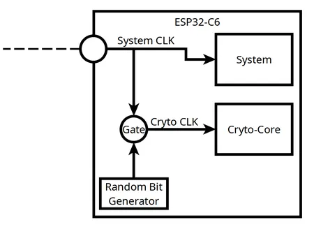
If, during a particular system clock tick, a difference between the crypto-core being clocked and the crypto-core being gated can be observed, an attacker could accurately predict when leakages are likely to occur.
The following graph depicts, at a given timestamp, the distributions of the measured samples under two configurations:
SEC_DPA_OFF, the clock randomization isn’t enabled.SEC_DPA_LOW, the clock randomization is enabled.
A clear difference can be observed between the two distributions. It seems reasonable to assume that, for the SEC_DPA_LOW security level, all samples below 120 units of current (i.e., when the system consumes less current than this threshold) correspond to instances when the crypto-core clock was gated.
With this understanding, it becomes possible to classify the traces into distinct groups, each corresponding to a similar pattern of the crypto-core clock.
Conducting a CPA attack for each of these groups is likely to yield strong results, as all traces within a group are synchronized.
The correlation values obtained from each attack can be combined (multiplied) to derive the final correlation results.
SEC_DPA_LOW Results
The target has been configured with the SEC_DPA_LOW security level, and once again, around 600k measurements cycles have been performed. For both of the targeted rounds, all 16 bytes can successfully be recovered.
Detailed results for this attack, as well as supplementary information, are available on the ESP32-C6 (SEC_DPA_LOW) Detailed Results page.
SEC_DPA_HIGH Results
Configuring the system with SEC_DPA_HIGH yields very similar results, and attacking the first two rounds enables the recovery of all bytes.
Detailed results for this attack, as well as supplementary information, are available on the ESP32-C6 (SEC_DPA_HIGH) Detailed Results page.
Conclusion
The countermeasures implemented to protect the ESP32-C6 against side-channel attacks don’t appear to be effective. The masking countermeasure doesn’t seem to have much impact, while the hiding countermeasure can be undermined by guessing the behavior of the crypto-clock.
Considering the above, I would say the ESP32-C6 does not look much more secure than the ESP32-C3.
With that said, the XTS mode of encryption forces once again to perform a new attack for every 128-byte block.
However, my next article will demonstrate that having control over a limited amount of flash data is sufficient to execute arbitrary code and extract the remaining content, even when the Secure Boot feature of the system is enabled.
Conclusion
Here, the publicly known side-channel attack against the ESP32 has been replicated using only inexpensive and custom hardware.
As suspected, the ESP32-C3 is also affected by a similar side-channel attack. However, the use of the XTS mode of encryption makes things more difficult for the attacker, and a given attack can only be employed to decrypt a specific 128-byte block at a time.
The ESP32-C6 supposedly embedded side-channel countermeasures in the form of:
- A masking countermeasure.
- A hiding countermeasure (clock randomization).
These countermeasures don’t appear to be effective, and the ESP32-C6 can be exploited similarly to the ESP32-C3, while still benefiting from the added security of the XTS mode of encryption.
However, the next article in this series will demonstrate that decrypting only a few of the XTS 128-byte blocks can be sufficient to extract the cleartext content of the entire external flash.
Disclosure Timeline
Espressif has been contacted to disclose the attack detailed in this article, along with the method disclosed in the next one.
The process outlined in the Espressif Security Incident Response Document has been followed.
- 07-Aug-2023: A first email was sent to Espressif.
- 28-Aug-2023: After several follow-up emails, Espressif started analyzing the issue.
- 15-Sept-2023 ~ 17-Nov-2023: Several technical exchanges took place. An ESP CPA Board unit and associated cartridges have been shipped to Espressif’s R&D center in Shanghai.
- 20-Nov-2023: The bug bounty team at Espressif deemed this research eligible for a reward, granting $2,229.
- 13-Dec-2023: Espressif shared a draft revision of a security advisory.
- 08-Jan-2024: Espressif published the final advisory.
Appendix
Leakage Assessment
Following a discussion with Espressif, a more thorough assessment of the leakages originating from the ESP32-C3 and ESP32-C6 has been performed.
The goal was to understand the actual impact of the masking countermeasure implemented in the ESP32-C6.
The results are available below:
Bibliography
Karim M. Abdellatif, Olivier Hériveaux, and Adrian Thillard. Unlimited results: breaking firmware encryption of esp32-v3. Cryptology ePrint Archive, Paper 2023/090, 2023. URL: https://eprint.iacr.org/2023/090. ↩ 1 2 3 4 5
Chao Luo, Yunsi Fei, and A. Adam Ding. Side-channel power analysis of xts-aes. In Design, Automation & Test in Europe Conference & Exhibition (DATE), 2017, volume, 1330–1335. 2017. doi:10.23919/DATE.2017.7927199. ↩
Qizhi Tian, Maire O'neill, and Neil Hanley. Can leakage models be more efficient? non-linear models in side channel attacks. In 2014 IEEE International Workshop on Information Forensics and Security (WIFS), volume, 215–220. 2014. doi:10.1109/WIFS.2014.7084330. ↩
Jason Waddle and David Wagner. Towards efficient second-order power analysis. In Cryptographic Hardware and Embedded Systems - CHES 2004: 6th International Workshop Cambridge, MA, USA, August 11-13, 2004. Proceedings, volume 3156 of Lecture Notes in Computer Science, 1–15. Springer, 2004. URL: https://iacr.org/archive/ches2004/31560001/31560001.pdf, doi:10.1007/978-3-540-28632-5_1. ↩